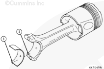
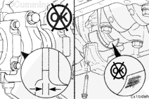
Install the upper bearing shell in the connecting rod. If used bearing shells are to be installed, each bearing shell must be installed in its original location.
NOTE: The tang (1) of the bearing shell must be in the slot (2) of the rod.
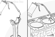
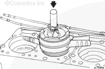
Lubricate the piston and the ring assembly by hand with clean 15W-40 lubricating oil. Dipping is okay, but draining is very difficult because the piston does not have drain holes. If dipping, only dip up to the pin bore, then hand lubricate it and the remaining skirt.
Do not use a hammer or its equivalent to install the piston into the cylinder liner. The piston rings can be damaged.
Install the connecting rod into the cylinder liner and push the piston down. If the piston does not move freely, remove the piston.
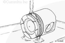
Inspect for broken or damaged rings.
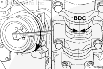
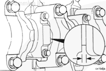
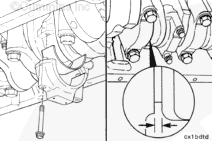
When installing the connecting rod, pay close attention to make sure the rod is aligned with the crankshaft rod journal. If the rod is misaligned, it can bind or scrape the crankshaft connecting rod journal side walls.
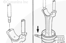
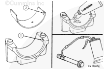
The tang (2) of the bearing must be in the slot (1) of the connecting rod cap.
Lubricate the bearing shell with Lubriplate® 105, or equivalent. Lubricate the connecting rod capscrew threads and the washer face with 15W-40 lubricating oil.
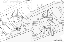
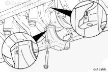
The connecting rod cap alpha characters must match the alpha characters on the connecting rod and must be installed with the characters aligned to prevent damage to the connecting rods and crankshaft. The locking tang of the connecting rod cap must be toward the camshaft side of the cylinder block.
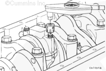
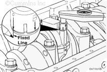
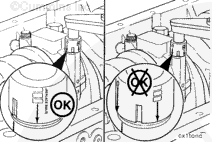
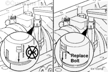
The connecting rod has changed on the 1994 Certification Level engine to accommodate the increased loading of the articulated pistons. The torquing procedure for the connecting rod capscrews has also changed. The new torque specification is 129 N•m [95 ft-lb] plus 60 degrees ± 5 degrees.
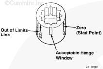
To facilitate this new torquing procedure, the torque angle socket gauge, Part Number 3824520, was developed.


 CAUTION
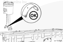


;)
;)
;)
;)
;)
;)
;)
;)
;)
;)
;)
;)
;)
;)
;)
;)
;)
;)
;)
;)
;)
;)
;)
;)
;)
;)
;)
;)
;)
;)
;)
;)
;)
;)
;)
;)