Table of Contents

Install


Install

TOC

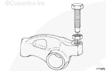
Install the adjusting screw and the lock nut in each rocker lever. Do not tighten the lock nuts.


SMALL | MEDIUM | LARGE

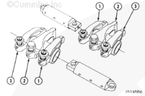
Install the exhaust (1), injector (2), and intake (3) rocker levers onto the shaft.

The two levers closest to the center of the rocker housing are the intake valve rocker levers. The levers closest to the end of the rocker housing are the exhaust valve rocker levers.


SMALL | MEDIUM | LARGE
   

 CAUTION 

If the adjusting screws protrude beyond the maximum listed below, the push rods can be damaged when the rocker shaft capscrews are tightened. Do not attempt to install the rocker lever shaft assemblies without resetting the lash.

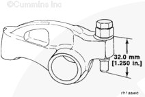
Loosen the rocker lever adjusting screws so there is a maximum of 32 mm [1.250 in] from the top surface of the lever and the ball end of the adjusting screw.

 
SMALL | MEDIUM | LARGE
   

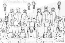
Place the rocker lever assembly over the dowel pin and dowel ring located in the rocker housing.

NOTE: Do not damage the dowel pin and ring located in the rocker housing.

 
SMALL | MEDIUM | LARGE
   

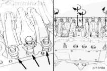
Make sure the push rods are in the cam follower sockets and align the push rods with the injector and valve rocker lever adjusting screws.

Alternately tighten the rocker shaft capscrews:

Torque Value:
  1. 54 n.m    [40 ft-lb]
  2. 108 n.m    [80 ft-lb]
  3. 156 n.m    [115 ft-lb]


SMALL | MEDIUM | LARGE
   

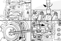
Adjust the valves and injectors. Refer to Procedure 003-004 in Section 3.


SMALL | MEDIUM | LARGE


Last Modified:  20-Sep-2011
Feedback / Help