Table of Contents

Install


Install

TOC

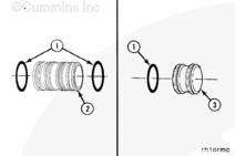
Install two o-rings (1) on each of the two water tubes (2). Install one o-ring (1) on each of the two water plugs (3).

Install the o-rings on the water tubes and plugs.


SMALL | MEDIUM | LARGE

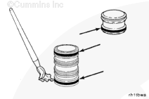
Apply soap to the o-rings on the tubes and plugs.

 
SMALL | MEDIUM | LARGE
   

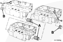
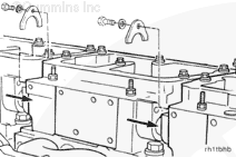
Install the water tubes (A) in the front of the Number 2 and Number 3 rocker lever housings. Install the plugs (B) in the front to the Number 1 rocker lever housing and in the rear of the Number 3 rocker lever housing.


SMALL | MEDIUM | LARGE
   

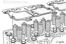
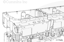
Install new rocker lever housing gaskets onto the cylinder heads.


SMALL | MEDIUM | LARGE
   

Install the rocker lever housings.


SMALL | MEDIUM | LARGE
   

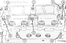
Tighten the rocker lever housing capscrews in sequence as illustrated (1 thru 6).

Torque Value:  115  n.m  [85 ft-lb]

Tighten the rocker lever housing capscrews in sequence as illustrated (7 and 8).

Torque Value:  47  n.m  [35 ft-lb]


SMALL | MEDIUM | LARGE
   

Use jumper tube removal tool, Part Number 3823819, to slide the two water tubes into the adjacent water manifold.

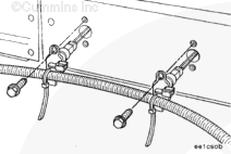
Install the two water tube retainer clamps.

Install and tighten the retainer clamp capscrews.

Torque Value:  45  n.m  [33 ft-lb]

Install the injectors.


SMALL | MEDIUM | LARGE
   

Install the wiring harness pass through. Tighten the 5/16-inch pass through mounting capscrew.

Torque Value:  15  n.m  [133 in-lb]


SMALL | MEDIUM | LARGE
   

 WARNING 

The injector must be fully seated before installing the hold down clamp. The hold down clamp can not pull the injector into the bore. Engine damage can occur if the injector is not fully seated.

Install the hold down clamp capscrew.

Torque Value:  41  n.m  [30 ft-lb]


SMALL | MEDIUM | LARGE
   

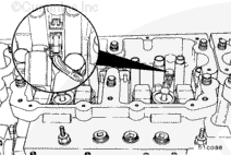
Take care to route the injector solenoid leads to avoid contact with the valve and injector push tubes.

 
SMALL | MEDIUM | LARGE
   

Connect the injector solenoid wiring to the rocker lever housing pass through.

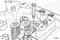
Install the valve crossheads.


SMALL | MEDIUM | LARGE
   

 CAUTION 

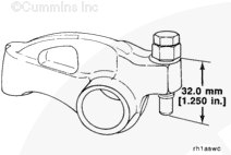
If the adjusting screws protrude beyond the maximum listed below, the push rods can be damaged when the housing capscrews are tightened. Do not attempt to install the rocker lever shaft assemblies again without resetting the lash.

Loosen the rocker lever adjusting screws so there is a maximum of 32.0 mm [1.25 in] from the top surface of the lever and the ball end of the adjusting screw.

 
SMALL | MEDIUM | LARGE
   

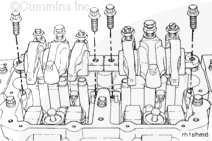
Install the rocker lever assemblies. Refer to Procedure 003-009 in Section 3.


SMALL | MEDIUM | LARGE
   

Adjust the valves and injectors. Refer to Procedure 003-004 in Section 3.


SMALL | MEDIUM | LARGE
   

Install the coolant thermostat housing. Refer to Procedure 008-014 in Section 8.


SMALL | MEDIUM | LARGE
   

Connect the wiring harness.


SMALL | MEDIUM | LARGE


Last Modified:  21-Sep-2011
Feedback / Help