Table of Contents

Preparatory Steps
Remove
Inspect for Reuse
Install
Finishing Steps


Preparatory Steps

TOC
 WARNING 

Batteries can emit explosive gases. To reduce the possibility of personal injury, always ventilate the compartment before servicing the batteries. To reduce the possibility of arcing, remove the negative (-) battery cable first and attach the negative (-) battery cable last.


SMALL | MEDIUM | LARGE


Remove

TOC

Remove the push rods.

NOTE: To prevent increased wear, mark each push rod as it is removed so it can be installed back in its original location.


SMALL | MEDIUM | LARGE


Inspect for Reuse

TOC

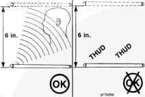
Inspect for engine oil in the push rods as follows:

  • Hold the push rod horizontally and drop it from a height of 6 inches onto a concrete floor or a metal surface.
  • The push rod can be used if a ringing sound is heard.
  • If a dull (or non-ringing) sound is heard, the push rod contains engine oil and must be discarded.


SMALL | MEDIUM | LARGE
   

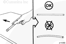
Inspect the straightness of the push rod by rolling it on a level bench. Replace the push rod if it is bent. Do not use a bent push rod.


SMALL | MEDIUM | LARGE
   

Inspect the socket end of the push rod for uneven wear, scratches, or separation of the insert from the tube.

If a worn push rod is found, the mating adjusting screw must also be replaced.

When parallel scratches are found in the contact area, the push rods must be replaced.


SMALL | MEDIUM | LARGE
   

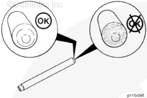
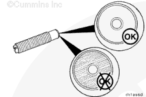
Inspect the ball end of the push rod.

The contact area must show a smooth seating pattern.

If the ball end of the push rod has parallel grooves and scratches or a nipple in the center, the push rod must be replaced. If a worn push rod is found, the mating cam follower socket must be replaced. Refer to Procedure 004-001 in Section 4.


SMALL | MEDIUM | LARGE


Install

TOC

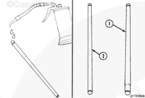
Use clean 15W-40 oil to lubricate the ball end of the push rods.

NOTE: The injector push rods (1) are larger in diameter than the valve push rods (2).


SMALL | MEDIUM | LARGE
   

Install the push rods into the corresponding numbered location.


SMALL | MEDIUM | LARGE
   

Inspect the adjusting screw. The contact area must be smooth with an even seating pattern.

If parallel scratches are found in the contact area, the adjusting screw must be replaced. This condition is normally found with worn push rods that will also require replacement.


SMALL | MEDIUM | LARGE
   

 CAUTION 

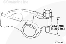
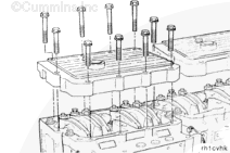
If the adjusting screws protrude beyond the maximum listed below, the push rods can be damaged when the housing capscrews are tightened. Do not attempt to install the rocker lever shaft assemblies again without resetting the lash.

Loosen the rocker lever adjusting screws so there is a maximum of 32.0 mm [1.25 in] from the top surface of the lever and the ball end of the adjusting screw.

 
SMALL | MEDIUM | LARGE
   

Install the rocker lever cover gasket. The rocker lever cover gaskets can be used again if not damaged.


SMALL | MEDIUM | LARGE


Finishing Steps

TOC
 WARNING 

Batteries can emit explosive gases. To reduce the possibility of personal injury, always ventilate the compartment before servicing the batteries. To reduce the possibility of arcing, remove the negative (-) battery cable first and attach the negative (-) battery cable last.


SMALL | MEDIUM | LARGE


Last Modified:  21-Sep-2011
Feedback / Help