Table of Contents

Remove
Clean and Inspect for Reuse
Install


Remove

TOC

Remove the oil transfer tube. Refer to Procedure 007-040 in Section 7.


SMALL | MEDIUM | LARGE

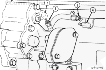
Disconnect the pressure signal line (1) from the lubricating pump fitting (2).

Disconnect the rifle pressure supply line (3) from the oil rifle fitting (4).


SMALL | MEDIUM | LARGE
   

Disconnect the viscosity sensor drain line from the cylinder block fitting.


SMALL | MEDIUM | LARGE
   

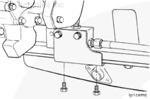
Remove the two mounting bracket capscrews from the pan rail.

Remove the entire assembly from the engine.


SMALL | MEDIUM | LARGE
   

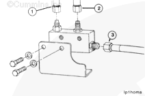
Remove the hoses and bracket from the viscosity sensor.

  1. Main oil rifle pressure
  2. Modified pressure signal to pressure regulator
  3. Return to oil pan.


SMALL | MEDIUM | LARGE


Clean and Inspect for Reuse

TOC
 WARNING 

When using solvents, acids, or alkaline materials for cleaning, follow the manufacturer's recommendations for use. Wear goggles and protective clothing to reduce the possibility of personal injury.

Use ultrasonic cleaners, Part Number 337665 or 3375001, and ultrasonic cleaner solution, Part Number 33750003, to clean the viscosity sensor.


SMALL | MEDIUM | LARGE
   

 WARNING 

When using solvents, acids, or alkaline materials for cleaning, follow the manufacturer's recommendations for use. Wear goggles and protective clothing to reduce the possibility of personal injury.

Use mineral spirits to neutralize the solution after cleaning.

 
SMALL | MEDIUM | LARGE
   

Inspect the flex lines and fittings for plugging or restriction.

Clean or replace any obstruction parts.


SMALL | MEDIUM | LARGE
   

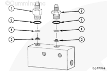
Remove the viscosity sensor fittings (1) and (2).

Remove and inspect the filter screen (3).

Replace damaged or plugged screens.


SMALL | MEDIUM | LARGE
   

Remove the viscosity sensor fitting (1).

Inspect the injector orifice plug (3) for damage or restriction.

Replace the injector plug (3) and gasket (4).


SMALL | MEDIUM | LARGE
   

 WARNING 

Wear appropriate eye and face protection when using compressed air. Flying debris and dirt can cause personal injury.

Use compressed air to blow through each port to remove any remaining debris.


SMALL | MEDIUM | LARGE
   

Install the filter screens (3) and screen retainers (4) in the viscosity sensor.

Lubricate the o-rings with vegetable oil.

Install the fittings (1) and (2), with new o-rings (5), and tighten.

Torque Value:
  1. 24 n.m    [212 in-lb]
  2. 18 n.m    [159 in-lb]


SMALL | MEDIUM | LARGE
   

Install the injector orifice plug (3) and gasket (4).

Lubricate the o-ring with vegetable oil.

Install the fitting (1), using a new o-ring (2) and tighten.

Torque Value:  31  n.m  [23 ft-lb]


SMALL | MEDIUM | LARGE


Install

TOC

Install the bracket to the viscosity sensor. Install the two bracket capscrews and tighten.

Torque Value:  27  n.m  [239 in-lb]

Connect the flexible hoses to the viscosity sensor fittings.

Do not allow dirt or debris to enter the oil lines.

Main oil rifle pressure. Modified pressure signal to pressure regulator. Return to oil pan.


SMALL | MEDIUM | LARGE
   

Install the entire assembly with flex hoses attached to the cylinder block pan rail.

Install the two capscrews and tighten.

Torque Value:  68  n.m  [50 ft-lb]


SMALL | MEDIUM | LARGE
   

Connect the sensor drain line (1) to the tee fitting on the cylinder block.


SMALL | MEDIUM | LARGE
   

Connect the pressure signal line (1) to the lubricating pump fitting (2) and the rifle pressure supply line (3) to the oil rifle fitting (4).


SMALL | MEDIUM | LARGE
   

Install the oil transfer tube. Refer to Procedure 007-040 in Section 7.


SMALL | MEDIUM | LARGE
   

Operate the engine until the water temperature reaches 82°C [180°F], and check for leaks.

The viscosity sensor controls the oil pressure signal to the lubricating pump pressure regulator.

It allows high oil rifle pressure with cold, thick oil, but normal oil rifle pressure with warm oil.

The high oil pressure with cold viscous oil highly improves oil fill of the STC injector tappets.

This provides maximum engine timing advancement and white smoke control. The sensor allows normal oil pressure when the oil is warm.

Effect of Viscosity Sensor on Main Oil Rifle Pressure
Oil Temperature
Low Idle Oil Pressure
High Idle Oil Pressure
0°C [32°F]
450 to 690 kPa [65 to 100 psi]
490 to 770 kPa [70 to 110 psi]
21°C [70°F]
350 to 590 kPa [50 to 85 psi]
380 to 660 kPa [55 to 95 psi]
93°C [200° F]
100 kPa [15 psi]
240 to 310 kPa [35 to 45 psi]


SMALL | MEDIUM | LARGE
   

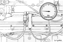
Connect an oil pressure gauge of known accuracy to the main oil rifle.


SMALL | MEDIUM | LARGE
   

Operate the engine until the oil temperature stabilizes.

Observe the oil rifle pressure as the temperature of the oil is increasing. Compare the results with the values given in the Effect of Viscosity Sensor on Main Oil Rifle Pressure table.

If the results do not agree with the table, verify that the base engine lubricating system is operating properly before removing the viscosity sensor.


SMALL | MEDIUM | LARGE
   

Verify that the base engine lubricating system if functioning properly by isolating the viscosity sensor from the system.

Disconnect the viscosity sensor to the lubricating pump line and the oil rifle to viscosity sensor line.

Plug both lines from the viscosity sensor.


SMALL | MEDIUM | LARGE
   

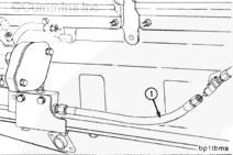
Connect a pressure signal line from the oil rifle to the lubricating pump.

Construct a flexible hose (1) of 305.0 mm [12.01 in] to connect the main oil rifle (3) to the lubricating oil pump (2).


SMALL | MEDIUM | LARGE
   

Operate the engine until the oil temperature stabilizes.

The temperature must be between 83°C [180°F] and 93°C [200°F].

Observe the oil rifle pressure as the oil temperature rises.


SMALL | MEDIUM | LARGE
   

Observe the oil pressure at the oil main rifle. The pressure must be as follows:

Oil pressure at idle (minimum allowable) 60 kPa [10 psi] at 93°C [200°F].

At no load governed speed: 240 to 310 kPa [35 to 45 psi].

If the pressure is within these specifications, the lubricating system is operating properly.


SMALL | MEDIUM | LARGE


Last Modified:  19-Oct-2011
Feedback / Help