Table of Contents

Remove


Remove

TOC

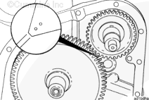
The timing marks on the accessory drive gear and the camshaft gear must be aligned so that the valve and the injector set marks on the accessory drive pulley show the correct adjustment position.

Timing marks can be seen through the gear cover straight thread plug inspection hole.

 
SMALL | MEDIUM | LARGE

Remove the accessory drive pulley. Refer to Procedure 009-004 in Section 9.

Remove the inspection hole straight thread plug in the gear cover.


SMALL | MEDIUM | LARGE
   

Check to make sure the timing marks on the camshaft gear and the accessory drive gear are aligned with each other.

If only the timing mark on the accessory drive gear is visible through the inspection hole, rotate the crankshaft one complete revolution in the direction of rotation to align the timing marks on the camshaft gear and the accessory drive gear.


SMALL | MEDIUM | LARGE
   

 CAUTION 

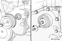
If the accessory drive dowel pin has not been correctly installed in the accessory drive shaft, the dowel pin must be removed before attempting to remove the accessory drive to prevent damage to the accessory drive bushing.


SMALL | MEDIUM | LARGE
   

Remove the five capscrews and the accessory drive assembly.

Clean the cylinder block and the accessory drive gasket surfaces.

 
SMALL | MEDIUM | LARGE
   

Remove the accessory drive seal. Refer to Procedure 001-003 in Section 1.


SMALL | MEDIUM | LARGE


Last Modified:  19-Sep-2011
Feedback / Help