Table of Contents

Preparatory Steps
Remove
Initial Check
Disassemble
Clean and Inspect for Reuse
Measure
Assemble
Install
Finishing Steps


Preparatory Steps

TOC
 WARNING 

Batteries can emit explosive gases. To reduce the possibility of personal injury, always ventilate the compartment before servicing the batteries. To reduce the possibility of arcing, remove the negative (-) battery cable first and attach the negative (-) battery cable last.



SMALL | MEDIUM | LARGE


Remove

TOC

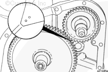
The timing marks on the accessory drive gear and the camshaft gear must be aligned so that the valve and the injector set marks on the accessory drive pulley show the correct adjustment position.

Timing marks can be seen through the gear cover straight thread plug inspection hole.

 
SMALL | MEDIUM | LARGE
   

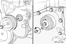
Remove the accessory drive pulley. Refer to Procedure 009-004 in Section 9.

Remove the inspection hole straight thread plug in the gear cover.


SMALL | MEDIUM | LARGE
   

Check to make sure the timing marks on the camshaft gear and the accessory drive gear are aligned with each other.

If only the timing mark on the accessory drive gear is visible through the inspection hole, rotate the crankshaft one complete revolution in the direction of rotation to align the timing marks on the camshaft gear and the accessory drive gear.


SMALL | MEDIUM | LARGE
   

 CAUTION 

If the accessory drive dowel pin has not been correctly installed in the accessory drive shaft, the dowel pin must be removed before attempting to remove the accessory drive to prevent damage to the accessory drive bushing.


SMALL | MEDIUM | LARGE
   

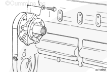
Remove the five capscrews and the accessory drive assembly.

Clean the cylinder block and the accessory drive gasket surfaces.

 
SMALL | MEDIUM | LARGE
   

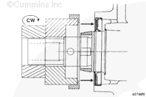
Remove the accessory drive seal. Refer to Procedure 001-003 in Section 1.


SMALL | MEDIUM | LARGE


Initial Check

TOC
 WARNING 

When using solvents, acids, or alkaline materials for cleaning, follow the manufacturer's recommendations for use. Wear goggles and protective clothing to reduce the possibility of personal injury.
 WARNING 

Wear appropriate eye and face protection when using compressed air. Flying debris and dirt can cause personal injury.

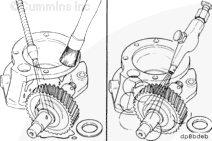
Remove all gasket material from surfaces (1) and (2).

Clean the exterior of the drive with solvent.

Dry with compressed air.


SMALL | MEDIUM | LARGE
   

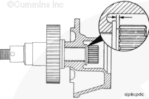
Measure the drive shaft end clearance.

Drive Shaft End Clearance

mmin
0.05MIN0.002
0.225MAX0.009

If the shaft end clearance does not meet these specifications, replace the drive unit.


SMALL | MEDIUM | LARGE
   

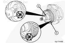
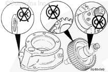
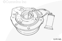
Inspect the housing for cracks or damaged mounting holes.

Inspect the drive gear (1) and splined coupling for damaged teeth and wear.

Inspect the shaft (2) for scratches, scoring, or other damage.

Replace as necessary.


SMALL | MEDIUM | LARGE


Disassemble

TOC
 CAUTION 

Install a 3/8-16 X 3/4-inch capscrew (1) without the washer into the shaft to prevent damage to the shaft while the gear is being removed.

If the accessory drive is being disassembled for gear or shaft replacement, inspect the housing.

Remove the special capscrew and washer.


SMALL | MEDIUM | LARGE
   

Use coupling puller, Part Number 3376663, to remove the splined coupling.

Use a three-jaw puller to remove the hub-type coupling.

Remove the capscrew.


SMALL | MEDIUM | LARGE
   

Remove the clamping washer.

Remove the gear and shaft assembly.

Remove the straight thread o-ring plugs from the housing.


SMALL | MEDIUM | LARGE


Clean and Inspect for Reuse

TOC
 WARNING 

When using solvents, acids, or alkaline materials for cleaning, follow the manufacturer's recommendations for use. Wear goggles and protective clothing to reduce the possibility of personal injury.
 WARNING 

Wear appropriate eye and face protection when using compressed air. Flying debris and dirt can cause personal injury.

Clean the parts with solvent.

Dry with compressed air.


SMALL | MEDIUM | LARGE
   

Inspect the parts for damage.

If the gear or the shaft is damaged it must be replaced.


SMALL | MEDIUM | LARGE
   

Inspect the shaft bore in the housing for scoring or damage.


SMALL | MEDIUM | LARGE


Measure

TOC

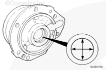
Measure the inside diameter of the shaft bore in the drive housing.

Drive Shaft Bore Inside Diameter

mmin
33.426MIN1.3160
33.515MAX1.3194


SMALL | MEDIUM | LARGE
   

Measure the drive shaft outside diameter.

Drive Shaft Journal Outside Diameter

mmin
Point 1 25.476MIN1.0030
 25.489MAX1.0035
Point 2 33.274MIN1.3100
 33.325MAX1.3120
Point 3 50.622MIN1.9930
 50.673MAX1.9950
Point 4 34.963MIN1.3765
 34.976MAX1.3770
Point 5 48.374MIN1.9045
 48.387MAX1.9050


SMALL | MEDIUM | LARGE
   

Measure the inside diameter of the splined coupling gear or the hub coupling.

Splined Coupling Inside Diameter

mmin
25.400MIN1.0000
25.425MAX1.0010

Hub Coupling Inside Diameter

mmin
25.424MIN1.0010
25.438MAX1.0015


SMALL | MEDIUM | LARGE
   

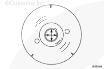
Measure the inside diameter of the drive pulley bore.

Drive Pulley Bore Inside Diameter

mmin
34.925MIN1.3750
34.945MAX1.3758


SMALL | MEDIUM | LARGE


Assemble

TOC

Use clean 15W-40 oil to lubricate the housing shaft bore.


SMALL | MEDIUM | LARGE
   

Use Lubriplate® 105, or equivalent, to lubricate the front thrust face on the housing.

Install the shaft and the gear.


SMALL | MEDIUM | LARGE
   

Use Lubriplate® 105, or equivalent, to lubricate the rear thrust face on the housing.

Install the clamping washer over the shaft.


SMALL | MEDIUM | LARGE
   

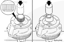
The splined-type coupling must be installed with the relieved area facing the clamping washer. The hub-type coupling must be installed with the drive tangs facing away from the clamping washer.

With the gear and shaft assembly supported in an arbor press, use a mandrel to install the coupling. Push the coupling until it touches the clamping washer.


SMALL | MEDIUM | LARGE
   

NOTE: The capscrew must contain an oil drilling if an air compressor is to be mounted on the engine.

Install the washer and capscrew.

Torque Value:  47  n.m  [35 ft-lb]


SMALL | MEDIUM | LARGE
   

Install the straight thread o-ring plugs in the housing.

Tighten the o-ring plugs.

Torque Value:
Aluminum Housing Plug Size: 5/16-24
  1. 3 n.m    [27 in-lb]
Torque Value:
Cast Iron Housing Plug Size: 5/16-24
  1. 6 n.m    [53 in-lb]
Torque Value:
Aluminum Housing Plug Size: 3/8-24
  1. 6 n.m    [53 in-lb]
Torque Value:
Cast Iron Housing Plug Size: 3/8-24
  1. 11 n.m    [97 in-lb]


SMALL | MEDIUM | LARGE
   

Rotate the shaft to check for correct assembly.

Measure the drive shaft end clearance at the end of the shaft for accurate measurement.

Drive Shaft End Clearance

mmin
0.10MIN0.004
0.225MAX0.009


SMALL | MEDIUM | LARGE
   

If the end clearance is not within specifications, make sure the coupling is positioned tightly against the clamping washer.

 
SMALL | MEDIUM | LARGE


Install

TOC

Rotate the crankshaft until the accessory drive timing marks on the camshaft gear are at approximately the 1:00 o'clock position.

 
SMALL | MEDIUM | LARGE
   

Install a new gasket onto the accessory drive assembly.

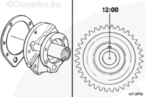
Place the accessory drive shaft dowel pin at approximately the 12:00 o'clock position when facing the shaft from the pulley end.


SMALL | MEDIUM | LARGE
   

Install the accessory drive assembly into the gear housing accessory drive mounting hole.

Check the alignment of the camshaft gear and the accessory drive gear timing marks.


SMALL | MEDIUM | LARGE
   

Install and tighten the five accessory drive mounting capscrews.

Torque Value:  61  n.m  [45 ft-lb]


SMALL | MEDIUM | LARGE
   

Install the accessory drive assembly into the gear housing accessory drive mounting hole.

Check the alignment of the camshaft gear and the accessory drive gear timing marks through the inspection hole in the gear cover.


SMALL | MEDIUM | LARGE
   

Install and tighten the five accessory drive mounting capscrews.

Torque Value:  61  n.m  [45 ft-lb]

Check the o-ring on the inspection hole plug. Replace the o-ring if it is damaged.

Install and tighten the plug.

Torque Value:  27  n.m  [239 in-lb]


SMALL | MEDIUM | LARGE
   

Install a new accessory drive seal into the gear cover. Refer to Procedure 001-003 in Section 1.


SMALL | MEDIUM | LARGE
   

Install the dowel pin into the accessory drive shaft (if removed).

Install the accessory drive pulley. Refer to Procedure 009-004 in Section 9.

 
SMALL | MEDIUM | LARGE


Finishing Steps

TOC
 WARNING 

Batteries can emit explosive gases. To reduce the possibility of personal injury, always ventilate the compartment before servicing the batteries. To reduce the possibility of arcing, remove the negative (-) battery cable first and attach the negative (-) battery cable last.


SMALL | MEDIUM | LARGE


Last Modified:  19-Sep-2011
Feedback / Help