Table of Contents

Preparatory Steps
Remove
Clean and Inspect for Reuse
Install
Finishing Steps


Preparatory Steps

TOC
 WARNING 

Batteries can emit explosive gases. To reduce the possibility of personal injury, always ventilate the compartment before servicing the batteries. To reduce the possibility of arcing, remove the negative (-) battery cable first and attach the negative (-) battery cable last.
 CAUTION 

If the accessory drive dowel pin has been installed in the accessory drive shaft, the dowel pin must be removed before attempting to remove the gear cover to prevent damage to the accessory drive bushing.



SMALL | MEDIUM | LARGE


Remove

TOC

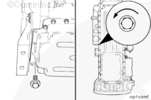
Remove the four capscrews which hold the oil pan to the gear cover.

Loosen all remaining oil pan mounting capscrews four to five turns.


SMALL | MEDIUM | LARGE
   

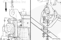
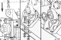
Use an overhead hoist or a hydraulic arm to support the engine.

Remove the capscrews which hold the front engine support to the crossmember of the equipment.


SMALL | MEDIUM | LARGE
   

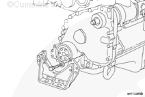
Remove the eight capscrews and the front engine support.


SMALL | MEDIUM | LARGE
   

 CAUTION 

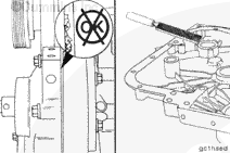
Use extreme care when releasing the oil pan gasket from the gear cover to prevent damage to the gasket. If the gasket is damaged, the oil pan must be removed and the gasket replaced. Refer to Procedure 007-025 in Section 7.

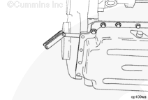
Insert a feeler gauge or a shim stock between the gear cover and the oil pan gasket. Move the feeler gauge or the shim stock back and forth to release the gasket from the gear cover.


SMALL | MEDIUM | LARGE
   

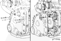
Remove one capscrew on each side of the gear cover, and install a 7/16 - 20 x 4-inch guide stud in each location to support the cover during removal.

Remove the remaining gear cover capscrews, and remove the gear cover.


SMALL | MEDIUM | LARGE
   

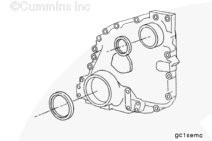
Remove the front crankshaft seal. Refer to Procedure 001-023 in Section 1.

Remove the accessory drive seal. Refer to Procedure 001-003 in Section 1.


SMALL | MEDIUM | LARGE


Clean and Inspect for Reuse

TOC

Clean the gasket surface of the cylinder block.

Clean the gear cover.


SMALL | MEDIUM | LARGE
   

Inspect the gear cover for cracks or other damage.


SMALL | MEDIUM | LARGE
   

Measure the accessory drive seal bore.

Accessory Drive Seal Bore Inside Diameter

mmin
80.962MIN3.1875
81.038MAX3.1905

NOTE: Replace the gear cover if the accessory drive seal bore is not within specifications.


SMALL | MEDIUM | LARGE
   

Measure the crankshaft seal bore.

Crankshaft Seal Bore Inside Diameter

mmin
120.611MIN4.7485
120.688MAX4.7515

NOTE: Replace the gear cover if the crankshaft seal bore is not within specifications.


SMALL | MEDIUM | LARGE
   

Measure the accessory drive bushing inside diameter.

Accessory Drive Bushing Diameter

mmin
39.75MIN1.9990
39.90MAX2.0015

NOTE: Replace the bushing if it is not within specifications. Refer to Procedure 001-066 in Section 1.


SMALL | MEDIUM | LARGE


Install

TOC

Install one 7/16 - 20 x 4-inch guide stud into each side of the gear cover mounting flange to align the cover.

Install the gear cover gasket over the guide studs and the dowel pins.

NOTE: Use a film of Lubriplate® 105, or equivalent, to hold the gear cover gasket in place, if necessary.


SMALL | MEDIUM | LARGE
   

Install the gear cover and the mounting capscrews.

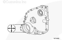
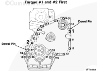
Tighten the capscrews to the following torque sequence as illustrated:

Torque Value:  68  n.m  [50 ft-lb]

Cut off the ends of the gasket even with the oil pan mounting flange.


SMALL | MEDIUM | LARGE
   

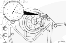
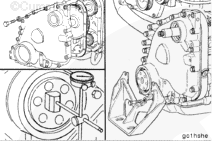
Mount a dial indicator on the front face of the crankshaft. Place the indicator plunger against the oil seal bore, and set the dial indicator at "0" (zero).

Rotate the crankshaft one complete revolution while monitoring the indicator. Use the accessory drive nut to bar the engine over. The total indicator reading must not exceed 0.38 mm [0.015 in].


SMALL | MEDIUM | LARGE
   

If the total indicator reading exceeds 0.38 mm [0.015 in] remove the gear cover. Check the cover and the housing for nicks or burrs.

Clean the gear cover and the housing surfaces thoroughly.


SMALL | MEDIUM | LARGE
   

Repeat the gear cover installation procedure and check the total indicator reading again.

Install the front engine support and eight mounting capscrews.

Tighten the capscrews.

Torque Value:  68  n.m  [50 ft-lb]


SMALL | MEDIUM | LARGE
   

Lower the engine to the crossmember. Install and tighten the capscrews which hold the front engine support to the crossmember. Refer to the OEM service manual for torque specifications.

Install the front crankshaft seal. Refer to Procedure 001-023 in Section 1.


SMALL | MEDIUM | LARGE


Finishing Steps

TOC
 WARNING 

Batteries can emit explosive gases. To reduce the possibility of personal injury, always ventilate the compartment before servicing the batteries. To reduce the possibility of arcing, remove the negative (-) battery cable first and attach the negative (-) battery cable last.
 CAUTION 

If the accessory drive dowel pin has been installed in the accessory drive shaft, the dowel pin must be removed before attempting to remove the gear cover to prevent damage to the accessory drive bushing.


SMALL | MEDIUM | LARGE


Last Modified:  15-Mar-2012
Feedback / Help