Table of Contents

Initial Check
Preparatory Steps
Remove
Install
Finishing Steps


Initial Check

TOC

Check the thermatic fan annually.

NOTE: Dual control systems are required for automatic radiator shutters and thermatic fans. Shutters must open and fans turn "ON" whenever the intake manifold air temperature rises above its sensor set point. Either condition (high coolant temperature or high intake manifold temperature) must activate the shutters and/or fan.


SMALL | MEDIUM | LARGE

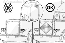
NOTE: If winterfronts or radiator covers are used, a minimum fixed opening of 77419 sq mm [120 sq in] is required at all times.

Shutterstat and thermatic fan controls must operate in the same temperature range as the thermostat with which they are used.

Install a master temperature gauge which is known to be accurate into the thermostat housing. A thermocouple can be used.


SMALL | MEDIUM | LARGE
   

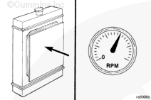
Restrict the radiator air flow.

Operate the engine at rated RPM.

 
SMALL | MEDIUM | LARGE
   

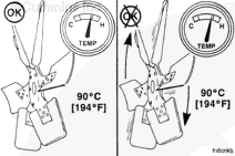
If the vehicle is air-conditioned, make sure the air conditioning is turned off to prevent continuous operation of the fan. When the coolant temperature reaches 93°C [200°F], check for fan engagement.

NOTE: Fan noise and air flow increase when the fan clutch engages.

 
SMALL | MEDIUM | LARGE
   

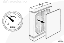
Return the engine to idle and remove the radiator air restriction.

 
SMALL | MEDIUM | LARGE
   

The fan clutch must disengage before the coolant temperature drops to 90°C [194°F]. Cummins Inc, recommends the fan disengage at 3°C [6°F] below the temperature stamped on the fan temperature sensor.

 
SMALL | MEDIUM | LARGE
   

If the fan does not operate within the temperature range indicated in the Thermal Control Settings Chart as illustrated, the fan clutch and controls must be checked. Refer to the OEM service manual.

 
SMALL | MEDIUM | LARGE


Preparatory Steps

TOC

Remove the cooling fan. Refer to Procedure 008-040 in Section 8.

NOTE: Do not discard the fan spacers. The spacers provide the thickness needed to install the fan in the correct position.


SMALL | MEDIUM | LARGE
   

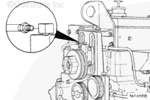
Disconnect the signal line.


SMALL | MEDIUM | LARGE


Remove

TOC

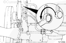
Loosen the capscrews which attach the fan hub to the bracket.

 
SMALL | MEDIUM | LARGE
   

Remove the fan hub adjusting capscrew and remove the fan belts.


SMALL | MEDIUM | LARGE
   

Loosen the fan hub capscrews and remove the fan hub.

 
SMALL | MEDIUM | LARGE


Install

TOC

Install the fan hub assembly onto the fan hub bracket. The capscrew must not be tightened at this time.


SMALL | MEDIUM | LARGE
   

Install the fan drive belts onto the fan hub and the accessory pulley. Do not tighten the belts.


SMALL | MEDIUM | LARGE
   

Install the fan hub adjusting screw.


SMALL | MEDIUM | LARGE


Finishing Steps

TOC

Install the cooling fan. Refer to Procedure 008-040 in Section 8.


SMALL | MEDIUM | LARGE
   

Install the fan hub signal line.

Tighten the fan belts. Refer to Procedure 008-002 in Section 8.


SMALL | MEDIUM | LARGE


Last Modified:  24-Oct-2011
Feedback / Help